Precision laser polymer/welding plastic is crucial in the electronics, automotive, and medical fields. From sterile catheter joining to the encapsulation/sealing of electronic parts or medical implants, this process can be applied to endless possibilities of polymers, plastics, and thicknesses. Several precision welding techniques are already implemented in the industry, with ultrasonic and laser welding being the most popular methods. Laser welding is certainly the most performant one as it enables a joining process that is contactless, precise, reliable, highly configurable, and residue free.
The basics of polymer laser welding
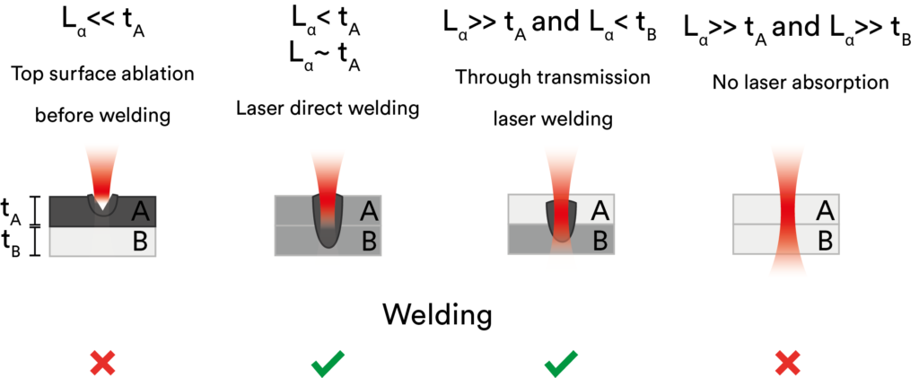
Laser welding plastic relies on the absorption of light that translates to thermal energy at the junction between the polymer layers (A and B). Welding occurs when at least one polymer layer is heated enough to soften the interface between the two polymers. Therefore, the two key parameters for laser welding of polymers are the optical absorption length (Lα) and the thickness (t) of the polymer. The absorption length is defined as the inverse of the absorption coefficient Lα = 1/α, which depends on the laser wavelength. The more light is absorbed by the polymer at a given wavelength, the smaller is the absorption length and vice-versa.

Depending on the value of the absorption length relative to the thickness of the polymer layer involved in the welding, five typical regimes are observed:
- (Lα << tA) case:
If the top polymer is absorbing too much the incident light, the heating may be too low at the welding interface. Laser ablation at the surface of the top polymer will occur before welding. - (Lα < tA) case:
If the top polymer is absorbing enough, polymer A (top layer) is heated enough to create a melt pool that extends to polymer B (bottom layer). This regime is referred to as “Laser direct welding”. - (Lα ~ tA) case:
To optimize the welding efficiency and speed in the laser direct welding regime, the laser absorption length (Lα) in the polymer should closely match the top layer thickness (tA). By doing so, no excess energy is lost and almost all of the available laser power is converted into heat in the top-layer. Selecting the right wavelength is thus crucial for good welding properties. - (Lα >> tA) and (Lα < tB) case:
If polymer A is transparent, not enough laser energy is converted into heat into the top layer. However, if polymer B is absorbing enough, a melt pool can be created at the interface. The “through transmission laser welding” technique refers to when the polymer A layer is transparent (or quasi-transparent) at the laser wavelength, but polymer B is absorbing enough. - (Lα >> tA) and (Lα >> tB) case:
Both layers are transparent and no welding occurs, unless very high laser powers are used. This is the case for most of the visible and near-IR lasers.
The mid-infrared advantage of welding
Lasers in the mid-infrared (> 2.5 µm) are more strongly absorbed by most of the clear polymers (See our other blog article), thus eliminating the need for additives or coatings. Pulsed fiber lasers near 3 µm provides also many advantages for welding applications in comparison with other types of mid-infrared lasers. As compared to CO2 lasers, 3 µm range pulsed fiber lasers have a smaller minimal spot size (> 3X smaller) and shorter pulse durations. These properties minimize the heat-affected zone and improve precision welding while avoiding discoloration due to excessive heating. Moreover, fiber lasers exhibit no warm-up time and high temporal stability compared to the CO2 laser counterpart. Most polymers at CO2 laser wavelength tend to be too absorbing (regime 1), often leading to ablation at the surface instead of welding. The 3 µm region is a sweet spot since the absorption length of most polymers is within the 10-500 µm range, closely matching the typical thicknesses found in the medical and electronic industry. Finally, fiber delivery can enable the 3D welding of complex curved parts together when coupled to a 6 axis robotic arm.
To demonstrate the capabilities of these lasers, we present clear-to-clear polymer welding with the Femtum Nano 2800. Prior to welding, the thin layers of polymer (thickness < 500 µm) are put in close contact by pressure. Using a scanner head, a laser line is scanned at the interface of both polymers at various speeds. The welding interface and strength are then studied for each combination of polymers.
Homogeneous welding (PET on PET)
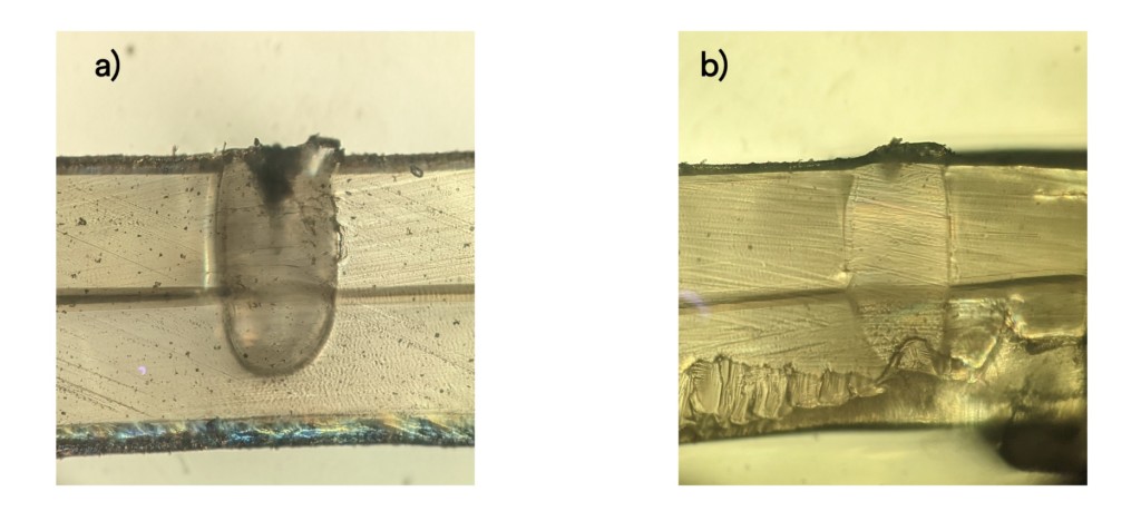
Fig. 2 shows the cross-section of the melt pool between two layers of PET sample with a thickness of 180 µm. Since PET is absorbing enough in the 3 µm region (> 70% absorption at 2800 nm for 180 µm thickness), most of the incident light is absorbed by the first layer, leading to a melt pool that extends to the other layer (case 2 above). The welding strength, which is proportional to the volume of the melt pool, can be controlled by the scanning speed and/or the laser power. In the picture below, a small bump can be observed on the top PET layer, but there is no sign of discoloration. For smaller scanning speeds the top surface is ablated, and discoloration is observed.

Dissimilar welding (PC on PET)
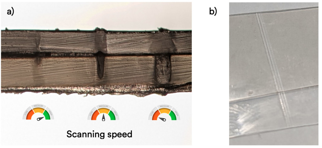
When two dissimilar polymers are welded together, the melt pool and weld strength depend strongly on the transmission properties of each polymer. In most cases, putting the polymer with the highest transmission at the laser wavelength (here the polycarbonate or PC) on the top layer is recommended for better weld results (scenario 4 above); if the polymer with higher absorption is on top, there is a risk of surface ablation before reaching the welding threshold (scenario 1 above). Fig. 3 A) presents a cross-section of the melt pools of a PC layer (125 µm) welded on a PET layer (180 µm) at three different speeds. Achieving a good welding strength while reducing the heat affected zone requires a compromise on the scanning speed. As shown in Fig. 3 B), no discoloration of the polymers can be observed for the three tested scanning speeds thanks to the unique properties of the Femtum Nano 2800.

Femtum’s unique laser welding capabilities
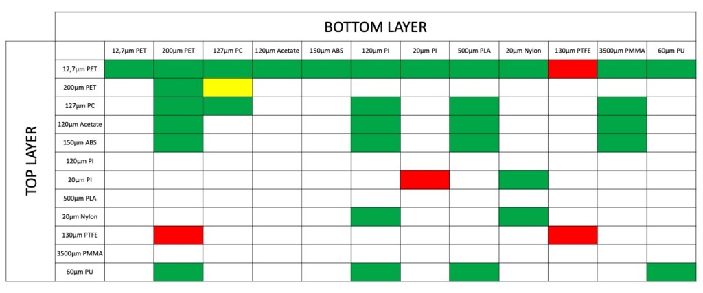
The precise joining of polymer layers using a laser is a complex process. Thanks to the unique feature of the Femtum Nano 2800, several types of polymers that use to be difficult to weld can now be easily welded without the use of additives. Here is a (non-exhaustive) table of the welds tested so far on various important polymers used in the medical, automotive, and electronic industries. These results were obtained in Femtum’s dedicated application lab. New capabilities of white-to-white, clear-to-clear, and white-to-clear polymer are now possible.

If you struggle with the precision welding of polymers, please contact us to discuss the unique laser welding capabilities of the Femtum lasers.
